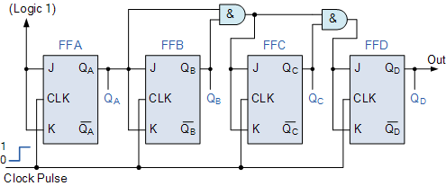
State Diagram Of 3 Bit Synchronous Counter
Counter synchronous flip flops jk asynchronous flop circuit implement configuration Diagram bit asynchronous circuit counter down flip jk digital using comment add Counter bit synchronous clock diagram bits rising solved output edge
Synchronous 3 bit Up/Down counter - GeeksforGeeks
Counter asynchronous bit flip flop binary logic two explain diagram timing clock output pulse eight electronics tutorial working states State diagram for the mod-11 synchronous counter. 3 bit synchronous down counter
Counter synchronous geeksforgeeks
Counter synchronous bit count shown such diagram belowCounter synchronous flop flops Asynchronous counterBinary care4you.
Synchronous 3 bit up/down counter3 bit synchronous down counter Synchronous negative triggered qca3-bit synchronous counter.

Counter bit state diagram flip binary using circuit flops table truth draw ff construct let
State counter diagram bit binary code module based diagrams build 3bit verilog wrote below wantSynchronous geeksforgeeks Synchronous 3-bit counter with negative edge-triggered qca circuitCounter synchronous geeksforgeeks.
Synchronous timing somaiyaCircuit design of a 4-bit binary counter using d flip-flops – vlsifacts Synchronous equation flop simplified geeksforgeeksSynchronous 3 bit up/down counter.

Draw a circuit diagram for 3-bit asynchronous binary down counter using
Counter synchronousSolved refer to the 3-bit synchronous counter diagram. Digital counterCounters circuitverse ripple flops truth 3bit counts circuits.
3 bit synchronous down counterWhat is synchronous counter? definition, circuit and operation of Synchronous flop geeksforgeeksBinary counter design stld/digital electronics.


Synchronous 3 bit Up/Down counter - GeeksforGeeks

Synchronous 3-bit counter with negative edge-triggered QCA circuit
3-bit Synchronous Counter

Circuit Design of a 4-bit Binary Counter Using D Flip-flops – VLSIFacts

State diagram for the MOD-11 synchronous counter. | Download Scientific
3 bit Synchronous Down Counter - GeeksforGeeks

Digital Counter | Synchronous and Asynchronous - M-Physics Tutorial

Synchronous 3 bit Up/Down counter - GeeksforGeeks

Counters - Digital Electronics
